Imo 11 Pin Relay Wiring Diagram
Each component should be set and linked to other parts in… Pin's 8 & 6 as normally open pin's 8 & 5 as normally closed.
I need a circuit with the following components A Pump â

5 a maximum switching power.
Imo 11 pin relay wiring diagram. With such an illustrative guide, you'll be capable of troubleshoot, stop, and complete your tasks easily. We identified it from trustworthy source. Car is a 2000 camaro.
One place where guys make a mistake imo (and the oems used to do it too) is trying to make a single diagram that has everything on it. How to wire a relay 8 pin timer wiring diagram din rail panel base ptf08a meishuoen rse miniature high power ac plugs and sockets 11 plug in with push 12v socket pyf08a china 2 pole imo precision controls cpc keetec ts manualzz it cr4 circuit the following components ba01c 8pin solution for every application 120ac volts coil fan factory. 85 and 86 are the coil pins while 30, 87, and 87a are the contact pins.
15 8 pin relay diagram. Buy h3cr a 11 pin dc 12v time relay 12vdc timer from. Mode 2 vehicle wiring cross reference chart* model year imo wire pin # imi wire pin # sec.
87 and 87a are the two contacts to which 30 will connect. Note that each pin is numbered. Otherwise, the arrangement will not function as it should be.
Here are a number of highest rated relay pin configuration pictures upon internet. Autonics at11en | timer relay 100 hr. So when wiring up these relays, the coil wire's will connect to pins 2 & 7 on the socket.
11 pin 3a spdt 120v | raptor supplies aliexpress.com : Is my wiring diagram correct? Timer relay is a time dependent magnetic switchyou will learn completely in this video about its use applicationtimer relay circuit diagramconnection.
Hooking them direct to battery is not ideal, so each switch needs a keyed 12v ignition source. Pin's 1 & 3 as normally open pin's 1 & 4 as normally closed. Unless printed on a very large sheet (2 x 3 feet would be the smallest i'd use), the information density is such that the finished diagram can be very hard to read.and it's easy for mistakes to creep in;
11 4 pin relay wiring diagram horn. Not merely will it help you attain your desired results quicker, but also make the complete procedure less difficult for everybody. 750xcxh 120a power relay se relays 12a 3pdt 120 vac hermetically sealed contacts hazardous location series schneider electric usa.
Adding driving lights that come on with the headlight main beam: Each component should be set and linked to other parts in specific way. Item 88hpx 35 110vdc 88hp series hermetically sealed plug in special purpose relays on struthers dunn.
Relay 11 pin wiring diagram wiring diagram is a simplified good enough pictorial representation of an electrical circuit it shows the components of the circuit as simplified shapes and the capacity and signal links with the devices. The high current circuit in this relay feeds. Since the common pin is determined, thus another one remaining pin in the connected pins detected in step 3 must be the normally closed (nc) pin.
We agree to this kind of relay pin configuration graphic could possibly be the most trending subject when we portion it in google lead or facebook. Now, all the pins of relay have been determined as in figure 9 below. Free delivery (over £100+vat, applies to.
This is the wiring diagrams. Imo rl01c 8 pin relay 230vac coil 2 pole changeover; Its submitted by executive in the best field.
If the coil is not activated, 30 will always be connected to 87a. 11 pin relay wiring diagram. 0c57b train horn wiring diagram for chevy digital resources.
11 pin relay generally known as 3c o relay means in this generally three common. Rear a c condenser fan relay wiring diagram pelican. Determine the common pin of the relay when the relay is activated.
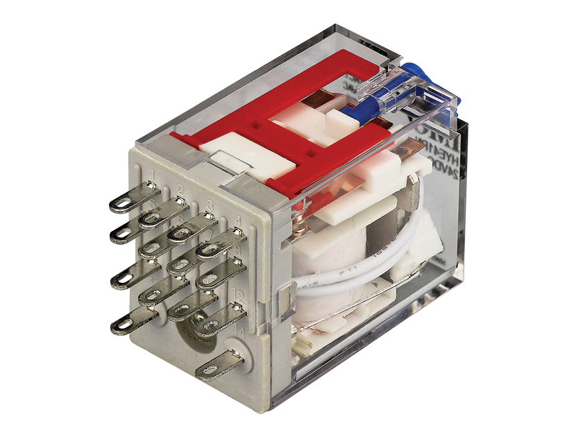
See my switch terminology page for more on contact arrangements if you need to. This simple circuit uses the power feed to the headlight main beam bulb as the trigger to energise a relay. Miniature intermediate power relay hye 10a switching capability 2kv dielectric strength (between coil and contacts).
11 10 9 8 7 wiring diagram wiring diagram 35.00 29.10 24.10 42.60 61.10 35.40 16.50 30.00 3.40 6.00 71.00 29.00 6.00 4.00 32. A timer relay is a combination of an electromechanical output relay and a control circuit the contacts will open or close before or after a preselected timed. Looking at the diagram, we see the pinout of a typical 12v relay.
Imo rl01c 8 pin relay 230vac coil 2 pole changeover. At the fog light relay you want to get rid of the blue/white wire, this is the power from the headlight relay, and replace it with another 12v source( i chose the cigarette lighter fuse). Imo 8 pin relay wiring diagram 8 pin relay wiring diagram.
The following diagrams show some common relay wiring schemes that use 4 pin iso mini relays. Is using a fused distribution block • led and flag • long endurance (min.
8 pin relay base diagram ptf08a jin kou direct. I dont like to cut and spice wires so i replaced the blue/white wire with a white one i had and moved the other off to the side. Wiring octal 11 pin latching relay cr4 discussion thread.
100,000 electrical operations) • 10a switching capability • industrial standard: When a relay contact is closed, there is a closed contact when the relay is not energized.
Relays & Bases City Electric Supply
2002 SC2 Disable DRL Forums
isuzu 4BD1T swap?! Page 34 IH8MUD Forum

Discovery 2 TD5 Wont start, nothing when turning ignition key
isuzu 4BD1T swap?! Page 34 IH8MUD Forum


7 Way Male Trailer Plug

45 2006 Chevy Cobalt Stereo Wiring Harness Wiring Niche

What did you do to your 900 today? Page 95 Polaris RZR
Rx8 red key light

45 2006 Chevy Cobalt Stereo Wiring Harness Wiring Niche
